Table of Contents

Preparatory Steps
Remove
Inspect for Reuse
Install
Finishing Steps


Preparatory Steps

TOC

NOTE: This procedure requires the Accessory Drive Removal and Installation Kit, Part Number 3824703.

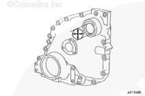
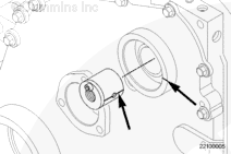
In order to correctly align the oil hole in the bushing with the hole in the gear cover, scribe a line on the outside diameter and face of the bushing, centered through the oil hole.

Scribe another line on the face of the gear cover, centered through the oil hole.

 
SMALL | MEDIUM | LARGE


Remove

TOC

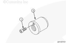
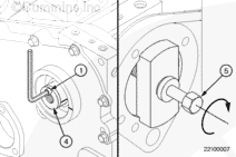
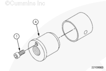
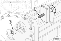
Tighten the 1/4-inch socket head capscrew (1) securely on the bushing driver mandrel (4).


SMALL | MEDIUM | LARGE
   

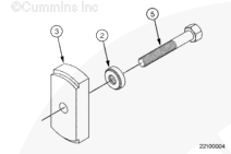
Assemble the bushing drive plate (3), thrust bearing (2), and the accessory drive forcing screws (5).

 
SMALL | MEDIUM | LARGE
   

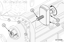
Position the bushing driver plate (3), thrust bearing (2), and the accessory drive forcing screw (5) over the block face where the accessory drive is mounted.

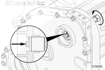
Rotate the accessory drive forcing screw (5) clockwise in the bushing driver mandrel (4).

 
SMALL | MEDIUM | LARGE
   

Insert a 1/4-inch Allen wrench in the capscrew (1) to keep the bushing driver mandrel (4) from rotating when turning the accessory drive forcing screw (5).

Turn the accessory drive forcing screw (5) clockwise while holding the bushing driver mandrel (4).


SMALL | MEDIUM | LARGE
   

Turn the forcing screw clockwise until the bushing slips out of the gear cover.

 
SMALL | MEDIUM | LARGE


Inspect for Reuse

TOC

Measure the gear cover accessory drive bushing bore.

Accessory Drive Bushing Bore Inside Diameter

mmin
54.03MIN2.127
54.05MAX2.128

NOTE: Replace the gear cover if the bore is not within specifications or if the bore is cracked or damaged.


SMALL | MEDIUM | LARGE


Install

TOC

Tighten the 1/4-inch socket head capscrew (1) securely on the bushing driver mandrel (4).

Insert a bushing over the bushing driver mandrel (4).

 
SMALL | MEDIUM | LARGE
   

Assemble the bushing driver plate (3), thrust bearing (2), and the accessory drive forcing screw (5).

 
SMALL | MEDIUM | LARGE
   

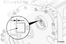
Align the scribe line on the bushing with the scribe line on the face of the gear cover.

 
SMALL | MEDIUM | LARGE
   

Position the bushing driver plate (3), thrust bearing (2), and the accessory drive forcing screw (5) over the block face where the accessory drive is mounted.

Rotate the accessory drive forcing screw (5) clockwise into the bushing driver mandrel (4).

NOTE: Make sure the scribe line on the bushing stays aligned with the scribe line on the face of the gear cover.

 
SMALL | MEDIUM | LARGE
   

NOTE: Make sure the scribe line on the bushing stays aligned with the scribe line on the face of the gear cover.

Insert a 1/4-inch Allen wrench in the capscrew (1) to keep the bushing driver mandrel (4) from rotating when turning the accessory drive forcing screw (5).

Turn the accessory drive forcing screw (5) clockwise while holding the bushing driver mandrel (4).

 
SMALL | MEDIUM | LARGE
   

Stop turning the accessory drive forcing screw (5) when the bushing becomes fully seated in the gear cover hole.

 
SMALL | MEDIUM | LARGE
   

 CAUTION 

Failure to align the bushing oil hole with the hole in the gear cover will stop oil from circulating through engine and cause damage to the engine.

Remove the bushing drive mandrel (4) from the gear cover by turning the accessory drive screw (5) counterclockwise.

Check the bushing oil hole alignment with the gear cover oil hole.

 
SMALL | MEDIUM | LARGE
   

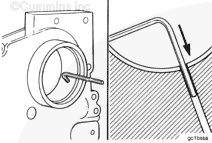
Use a 3.17 mm [0.125 in] diameter rod to check the position and the location of the oil hole in the bushing and the gear cover.

The rod must pass through the oil hole in the bushing and into the oil supply drilling in the gear cover.


SMALL | MEDIUM | LARGE


Finishing Steps

TOC
 
SMALL | MEDIUM | LARGE


Last Modified:  18-Nov-2011
Feedback / Help