|
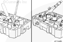
Loosen the locknut for the number 5 slave piston adjusting screw.
Install a dial indicator, Part Number 3375006, over the number 5 slave piston adjusting screw. Use the adapter, Part Number 3823826, to mount the dial indicator fixture to the engine brake.
Engine brake slave piston lash can not be set within the +/- .051 mm [.002 in] tolerance with a feeler gauge.
Exceeding the tolerance limits will result in low brake power, or possible exhaust valve/piston interference when set on the low side, or excessive component loading which could lead to damage, when set on the high side.
Engine brake slave piston lash must be set using the dial indicator method.
| 
 WARNING


 CAUTION
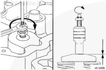


;)
;)
;)
;)
;)
;)
;)
;)
;)
;)
;)
;)
;)
;)
;)
;)
;)
;)
;)
;)
;)
;)
;)
;)
;)
;)
;)
;)
;)
;)
;)
;)
;)
;)
;)
;)