Table of Contents

Preparatory Steps
Remove
Clean and Inspect for Reuse
Install
Measure
Finishing Steps


Preparatory Steps

TOC
 WARNING 

Batteries can emit explosive gases. To reduce the possibility of personal injury, always ventilate the compartment before servicing the batteries. To reduce the possibility of arcing, remove the negative (-) battery cable first and attach the negative (-) battery cable last.


SMALL | MEDIUM | LARGE


Remove

TOC

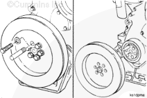
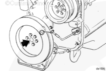
Remove one of the capscrews that hold the vibration damper and the pulley to the crankshaft.

Install a guide stud in the hole of the capscrew.

Remove the remaining five capscrews, the vibration damper, and the pulley.


SMALL | MEDIUM | LARGE


Clean and Inspect for Reuse

TOC
 WARNING 

When using solvents, acids, or alkaline materials for cleaning, follow the manufacturer’s recommendations for use. Wear goggles and protective clothing to reduce the possibility of personal injury.
 WARNING 

Wear appropriate eye and face protection when using compressed air. Flying debris and dirt can cause personal injury.

Clean the vibration damper with solvent and dry with compressed air.


SMALL | MEDIUM | LARGE
   

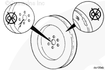
Inspect the vibration damper mounting area for cracks.

Check the housing for dents or raised surfaces.

Replace the damper if any damage is found.


SMALL | MEDIUM | LARGE
   

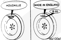
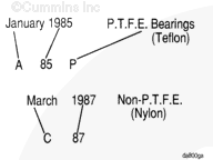
Record the vendor identification, date code, and part number.

 
SMALL | MEDIUM | LARGE
   

Using the date code, determine the type of bearing material in the damper.

  • Date codes followed by a “P” represent dampers with teflon bearing material.
  • Date codes that are not followed by a “P” represent dampers with nylon bearing material.
 
SMALL | MEDIUM | LARGE
   

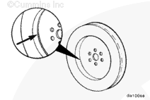
Determine if the vibration damper is a cast type or fabricated type.

Fabrication vibration dampers are the most common type and can be identified by a weld bead on the front center section of the damper where the housing joins the mounting flange.


SMALL | MEDIUM | LARGE
   

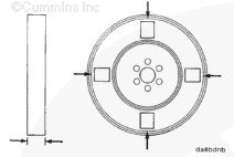
Remove the paint on both sides of the damper in four locations spaced 90 degrees apart.


SMALL | MEDIUM | LARGE
   

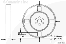
Measure and record the thickness at two points on each of the four locations.

  • Measure the thickness at 3.18 mm [0.125 in] from the outer lip.
  • Measure the thickness at 25.4 mm [1.0 in] from the outer lip.

This procedure will result in a total of eight measurements.

If the variations between any of the eight measurements exceeds 0.25 mm [0.010 in], or if the thickness at any point exceeds the maximum thickness dimensions indicated below in the table, the damper must be replaced.

Engine Model
Housing Type
Bearing Material
Maximum Thickness
NT
Cast
Teflon and nylon
39.37 mm [1.550 in]
NT
Fabricated
Nylon
39.88 mm [1.570 in]
NT
Fabricated
Teflon
39.62 mm [1.560 in]
NT and N14
Cast
Teflon and nylon
44.20 mm [1.740 in]
NT and N14
Fabricated
Teflon and nylon
44.24 mm [1.663 in]

Replace the small vibration damper with a large vibration damper, if the small vibration damper fails inspection or the engine experienced a camshaft nose failure.


SMALL | MEDIUM | LARGE
   

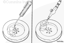
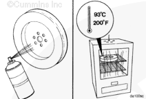
Spray the rolled lip of the vibration damper with crack detection developer, Part Number 3375434, or equivalent.

Heat the damper in an oven, rolled side down, at 93°C [200°F] for 2 hours.

 
SMALL | MEDIUM | LARGE
   

 WARNING 

Wear protective gloves when handling parts that have been heated to reduce the possibility of personal injury.

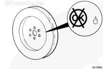
Remove the damper from the oven and check for fluid leakage around the rolled lip.

If the vibration damper has leaks, it must be replaced.


SMALL | MEDIUM | LARGE


Install

TOC

NOTE: Make sure the mounting surfaces of the crankshaft nose, vibration damper, and pulley are clean, dry, and free of burrs.

Install two guide pins into the end of the crankshaft.

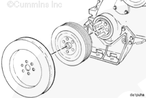
Install the pulley and vibration damper.


SMALL | MEDIUM | LARGE
   

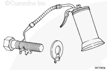
Lubricate the threads of the capscrews and washer with a film of SAE 15W-40 oil.

Install four of the six mounting capscrews.

Remove the two guide studs, and install the remaining two capscrews.


SMALL | MEDIUM | LARGE
   

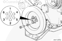
Install the washers and capscrews.

Keep the crankshaft from rotating and tighten the capscrews to the following torque values in the sequence illustrated.

Capscrew Size
SAE Grade Number
N•m [ft-lb]
5/8-inch
8
258 [190]


SMALL | MEDIUM | LARGE


Measure

TOC

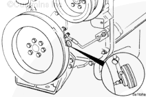
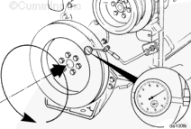
Install the dial indicator onto the gear cover, as illustrated, to measure the damper eccentricity.


SMALL | MEDIUM | LARGE
   

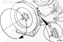
Rotate the crankshaft and record the indicator movement.

Replace the vibration damper if the eccentricity exceeds 0.10 mm [0.004 in] per 25.4 mm [1.0 in] of the damper diameter.


SMALL | MEDIUM | LARGE
   

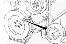
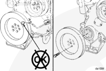
Install the dial indicator, as illustrated, to measure wobble.


SMALL | MEDIUM | LARGE
   

Push the crankshaft to the front or rear.

 
SMALL | MEDIUM | LARGE
   

Rotate the crankshaft 360 degrees, maintaining the position of the crankshaft (either toward the front or the rear) in relation to the block.

Record the total indicator motion.


SMALL | MEDIUM | LARGE
   

Replace the damper if the wobble exceeds 0.18 mm [0.007 in] per 25.4 mm [1.0 in] of radius.


SMALL | MEDIUM | LARGE


Finishing Steps

TOC
 WARNING 

Batteries can emit explosive gases. To reduce the possibility of personal injury, always ventilate the compartment before servicing the batteries. To reduce the possibility of arcing, remove the negative (-) battery cable first and attach the negative (-) battery cable last.


SMALL | MEDIUM | LARGE


Last Modified:  15-Sep-2011
Feedback / Help