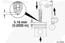
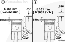
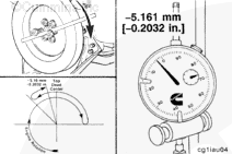
The static timing is relative to the amount of push tube travel remaining when the piston is 5.161 mm [0.2032 in], or 19 degrees before top dead center (TDC) on the compression stroke.
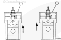
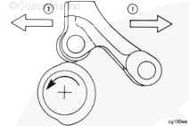
Advanced
timing (1) means the fuel is injected earlier into the cylinder during the compression stroke.
Retarded
timing (2) means the fuel injection occurs closer to TDC in the cylinder.
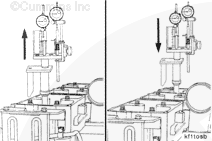
Injection timing changes are accomplished by
advancing
(1) or
retarding
(2) the cam follower action in relation to the piston position.
This is accomplished by changing the orientation of the camshaft lobe to the cam follower using different cam follower gasket thicknesses or offset camshaft gear keys.
NOTE: Gear train timing (index mark alignment)
always remains the same.
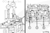
NOTE: The injection timing check is a measurement which determines the injector push rod travel in relation to the piston travel. Due to normal parts tolerances, it is necessary to check one cylinder for each cam follower housing.
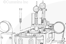
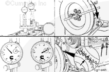
Align the swivel bracket with the injector clamp capscrew hole. Install the 6-inch swivel bracket capscrew. Finger-tighten the capscrew. Position the push rod plunger rod near the push rod.
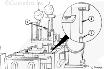
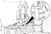
Loosen the support bracket (6), and slide the bracket down until the plunger rod (4) engages the injector push rod (7).
NOTE: The support bracket must be aligned with the vertical line on the clamp handle bracket. The push rod (7)
must be vertically aligned with the plunger rod (4).
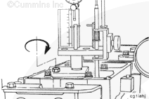
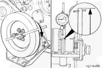
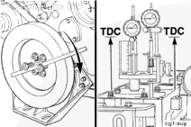
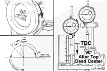
Determine the piston TDC on the compression stroke by rotating the crankshaft in the direction of engine rotation ( clockwise ) until the piston plunger reaches its uppermost position.
NOTE: Use only the crankshaft to rotate the engine. The use of the gears will result in false measurements. Gear lash
must
be closed up in the direction of normal rotation (crankshaft
clockwise ).
NOTE: The timing tool indicator needles will both start to move in the same direction of rotation as the piston approaches TDC if the cylinder is on the compression stroke. If both needles do
not move in the same direction, rotate the engine one complete revolution in the same direction of rotation.
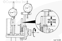
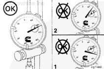
Both indicators must have a travel range of at least 6.35 mm [0.250 in] or the indicators will be damaged.
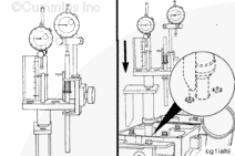
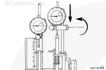
Place the piston travel dial indicator over the plunger rod with the contact tip in the center of the piston plunger rod. Lower the indicator to within 0.63 mm [0.025 in] of the fully compressed position.
Tighten the thumbscrew to hold the gauge in position.
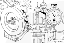
Rotate the crankshaft back and forth to make sure the piston is precisely at TDC on the compression stroke.
NOTE: Always set the dial indicator at "0" (zero) at TDC with the crankshaft having just been rotated in the direction of normal rotation
(clockwise) to reduce the timing errors due to gear backlash.
NOTE: TDC is indicated by the maximum
clockwise position of the piston travel indicator pointer.
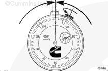
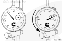
Set the dial indicator at "0" (zero). Lock the indicator face with the thumbscrew.
Place the push rod travel dial indicator in the center of the injector push rod plunger. Lower the indicator to within 0.63 mm [0.025 in] of a fully compressed position, and tighten the thumbscrew to hold the indicator in position.
NOTE: If the crankshaft is rotated beyond the -5.161 mm [-0.2032 in] position, the crankshaft must be rotated
counterclockwise back to 45 degrees BTDC.
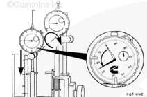
Rotate the crankshaft slowly in the direction of engine rotation ( clockwise ) until a reading of -5.161 mm [-0.2032 in] BTDC is reached on the piston travel dial indicator.
Compare the reading of the injector push rod travel indicator to the specification listed for the timing code.
NOTE: The push rod travel indicator is read in a
counterclockwise direction from "0" (zero). The total amount of travel represents the injection timing value.
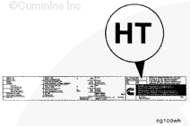
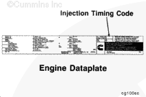
NOTE: To verify the correct injection timing for a particular engine, check the injection timing code on the engine dataplate. To acquire the timing specifications, refer to the Control Parts List (CPL).
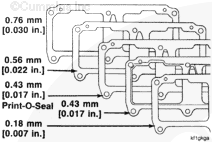
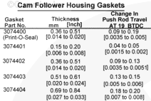
NOTE: The injection timing can be changed by removing the cam follower housing and by increasing or decreasing the gasket thickness. Each 0.18 mm [0.007 in] of gasket thickness affects injection timing by approximately 0.05 mm [0.002 in] indicator travel.
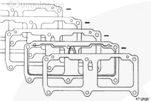
The accompanying chart lists the different cam follower housing gaskets, the gasket thickness, and approximate change in push rod travel at 19 degrees BTDC 0.2032-inch piston travel.
NOTE: The Print-O-Seal gasket (1) must be against the cylinder block with the sealing bead toward the cam follower housing. The minimum amount of gasket stack-up thickness which can be used is 0.43 mm [0.017 in] (one Print-O-Seal gasket). The maximum gasket stack-up thickness allowed is 2.03 mm [0.080 in].
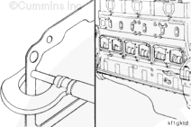
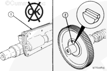
If you can not correct the injection timing by increasing or decreasing the thickness of the cam follower housing gaskets (1), an offset camshaft key (2) must be installed.
Refer to Procedure 001-013 in Section 1.
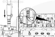
If the adjusting screws protrude beyond the maximum listed below, the push rods can be damaged when the rocker shaft capscrews are tightened. Do not attempt to install the rocker lever shaft assemblies again without resetting the lash.
Loosen the rocker lever adjusting screws so there is a maximum of 32.0 mm [1.25 in] from the top surface of the lever and the ball end of the adjusting screw.




 CAUTION






;)
;)
;)
;)
;)
;)
;)
;)
;)
;)
;)
;)
;)
;)
;)
;)
;)
;)
;)
;)
;)
;)
;)
;)
;)
;)
;)
;)
;)
;)
;)
;)
;)
;)
;)
;)
;)
;)
;)
;)
;)
;)
;)
;)
;)
;)
;)
;)
;)
;)
;)
;)
;)
;)
;)
;)
;)
;)
;)
;)
;)
;)
;)
;)
;)
;)
;)
;)
;)
;)
;)
;)