To reduce the possibility of personal injury, reduce the possibility of direct contact of hot oil with your skin.
WARNING
Some state and federal agencies have determined that used engine oil can be carcinogenic and cause reproductive toxicity. Avoid inhalation of vapors, ingestion, and prolonged contact with used engine oil. If not reused, dispose of in accordance with local environmental regulations.
WARNING
Do not remove the pressure cap from a hot engine. Wait until the coolant temperature is below 50°C [120°F] before removing the pressure cap. Heated coolant spray or steam can cause personal injury.
WARNING
Coolant is toxic. Keep away from children and pets. If not reused, dispose of in accordance with local environmental regulations.
When performing the following procedures, wear eye protection. Also, make sure the wire brush is rated for the RPM being used if the brush is motor driven.
CAUTION
Do not use abrasive paper to remove the carbon ring. Small particles of abrasive material will cause severe engine damage.
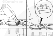
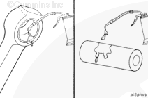
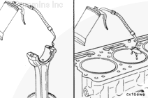
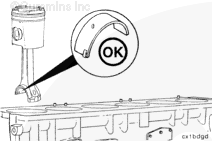
Plug the overhead oil rifle push tube cavities and coolant passages in the block, and use a rotary wire brush to remove the carbon ring from the top of the cylinder liner. Use a scraper that has an aluminum blade if a rotary wire brush is not available.
Use lint-free paper to remove all the broken wire bristles and loose carbon from the cylinders.
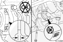
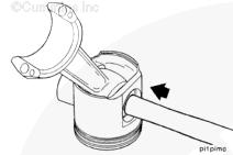
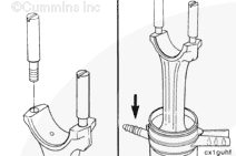
Install two connecting rod guide pins, Part Number 3375601.
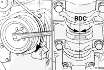
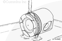
Use a dead blow mallet to push the rod away from the crankshaft.
Push the rod away from the crankshaft, cover the crankshaft rod journal, and push the rod until the piston rings are outside of the top of the cylinder liner.
The piston crown and skirt and connecting rod assemblies must be installed in the same cylinder number they were removed from to make sure there is a correct fit of worn mating surfaces if parts are used again. The piston skirt and crown must be reinstalled together.
Use a tag to mark the cylinder number from which each piston and rod assembly was removed. Make sure to mark both the skirt and crown on the piston.
NOTE: The pistons crown must have the cylinder numbers stamped on the piston top toward the camshaft side of the engine. The skirt must also be stamped so it can be matched with the piston crown.
The rod cap alpha characters must match the alpha characters on the connecting rod and must be installed with the characters aligned to prevent damage to the connecting rods and the crankshaft.
NOTE: Make sure the piston and rod assembly are correctly marked.
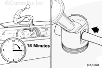
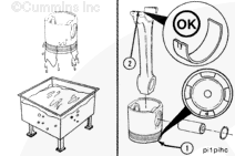
If the pin can not be removed, it is acceptable to put the piston in 66°C [150°F] water for 15 minutes and then manually remove the pin with a blunt tool.
Remove the piston from the water and lubricate the pin bore with clean 15W-40 oil.
Align the pin bore of the rod with the pin bore of the piston, and install the piston pin. Do not use a hammer to install the piston pin. The piston will be damaged.
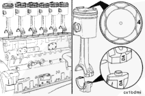
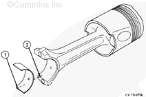
The cylinder number of the piston top (1) must be toward the bearing tang (2) side of the rod.
The pin must easily assemble without force; if it does not, inspect it for damage, dirt, poor lubrication, etc.
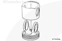
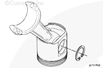
NOTE: The ring gap of each ring must not be aligned with the piston pin or with any other ring.
A cross-sectioned view of an oil control ring is shown. The two-piece oil control ring must be installed with the expander ring gap 180 degrees from the gap of the oil ring.
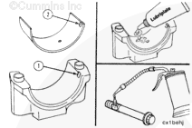
Install the upper bearing shell in the connecting rod. If used bearing shells are to be installed, each bearing shell must be installed in its original location.
NOTE: The tang (1) of the bearing shell must be in the slot (2) of the rod.
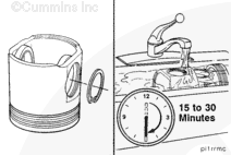
Lubricate the piston and the ring assembly by hand with clean 15W-40 oil. Dipping is okay, but draining is very difficult because the piston does not have drain holes. If dipping, only dip up to the pin bore and then hand lubricate it and the remaining skirt.
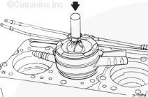
Do not use a hammer or its equivalent to install the piston into the cylinder liner. The piston rings can be damaged.
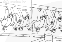
Install the connecting rod into the cylinder liner, and push the piston down. If the piston does not move freely, remove the piston. Inspect for broken or damaged rings.
When installing the connecting rod, pay close attention to make sure the rod is aligned with the crankshaft rod journal. If the rod is misaligned, it can bind or scrape the crankshaft connecting rod journal side walls.
The rod cap alpha characters must match the alpha characters on the connecting rod and must be installed with the characters aligned to prevent damage to the connecting rods and crankshaft. The locking tang of the connecting rod cap must be toward the camshaft side of the cylinder block.
Install the connecting rod caps and the capscrews.
The connecting rod has changed on the 1994 Certification Level engine to accommodate the increased loading of the articulated pistons. The torquing procedure for the connecting rod capscrews has also changed. The new torque specification is 129 N•m [95 ft-lb] plus 60 degrees ± 5 degrees.
To facilitate this new torquing procedure, the torque angle socket gauge, Part Number 3824520, was developed.
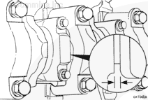
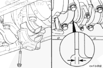
Measure the connecting rod side clearance. The side clearance must be between 0.140 and 0.33 mm [0.013 and 0.0055 in].
The connecting rod must move freely from side to side on the crankshaft journal. If the rod does not move freely, remove the rod cap and make sure the bearing shells are the correct size. Check for dirt or damage on the crankshaft and the bearing shells.
The lubricating oil system must be primed before operating the engine after any internal engine repairs to reduce the possibility of internal component damage. Do not prime the system from the bypass filter; the filter will be damaged.

 WARNING
 CAUTION


;)
;)
;)
;)
;)
;)
;)
;)
;)
;)
;)
;)
;)
;)
;)
;)
;)
;)
;)
;)
;)
;)
;)
;)
;)
;)
;)
;)
;)
;)
;)
;)
;)
;)
;)
;)
;)
;)
;)
;)
;)
;)
;)
;)
;)
;)
;)
;)
;)
;)
;)
;)
;)
;)
;)
;)
;)
;)
;)
;)
;)
;)
;)
;)
;)
;)
;)
;)
;)
;)
;)
;)
;)
;)
;)
;)
;)
;)
;)
;)
;)
;)